Resource assessment
Meteorological data
Meteorological data
~
Weather station
For a more detailed analyse of the renewable energy sources in a particular area, was developed a meteorological complex operating in automatic mode. A prototype has been installed on the territory of the "Red Lake" ski resort and is operating in a test mode. Data on wind and solar energy with an interval of 10 seconds are recorded in the station's memory, and also transmitted to the Internet in real time. Daily data reports are sent to a special email address for further processing.
As part of this program, a fundamentally new mobile device has been developed for year-round recording of the amount of solar energy entering the inclined surface.
As part of this program, a fundamentally new mobile device has been developed for year-round recording of the amount of solar energy entering the inclined surface.
Peltier effect
In 1834, the French watchmaker Jean Peltier discovered that when a direct current flows through the contact of two dissimilar conductors, heat is released or absorbed. The amount of heat released and its sign depend on the type of contacting substances, current strength and time of current flow, that is, the amount of heat released is proportional to the amount of charge passed through the contact:
dQ12 = P12Idt = − dQ21
dQ12 = P12Idt = − dQ21
The cause of the Peltier phenomenon is as follows: at the contact of two substances there is a contact potential difference, which creates an internal contact field. If a current flows through the contact, then this field will either facilitate the passage of current or interfere. If the current goes against the contact field, then the external source must expend additional energy, which is released in the contact, which will lead to its heating. If the current goes in the direction of the contact field, then it can be supported by this field, which does the work on the movement of charges. The energy required for this is taken from the substance, which leads to its cooling at the point of contact. The Peltier effect is most pronounced on the contacts of semiconductors with different types ( p or n ) of conductivity.
Here, the Peltier effect manifests itself in the interaction of conduction electrons, slowed down or accelerated in the contact potential of the pn junction, with thermal oscillations of atoms in the semiconductor array. As a result, depending on the direction of movement of the electrons and, accordingly, the current, heating or cooling of the section of the semiconductor directly adjacent to the junction ( pn or np junction) occurs .
The Peltier effect underlies the operation of a thermoelectric module (TEM). A single element of TEM is a thermocouple, consisting of one conductor (branch) of p- type and one conductor of n- type. When several such thermocouples are connected in series, the heat ( Qc), absorbed on the contact type n - p , stands out on the contact type p - n ( Qh). A thermoelectric module is a collection of such thermocouples, usually interconnected sequentially in current and in parallel in heat flux. Thermocouples are placed between two ceramic plates. The branches are soldered to copper conductive pads (skins), which are attached to special heat-conducting ceramics, for example, from aluminum oxide. The number of thermocouples can vary widely - from several units to several hundred, which allows you to create TEM with a cooling capacity of from tenths of a watt to hundreds of watts. Among the TEM materials, bismuth telluride has the highest thermoelectric efficiency, in which special additives, for example, selenium and antimony, are added to obtain the required type and conductivity parameters. Traditionally, the side to which the wires are attached is hot, and it is depicted from below.
The Peltier effect underlies the operation of a thermoelectric module (TEM). A single element of TEM is a thermocouple, consisting of one conductor (branch) of p- type and one conductor of n- type. When several such thermocouples are connected in series, the heat ( Qc), absorbed on the contact type n - p , stands out on the contact type p - n ( Qh). A thermoelectric module is a collection of such thermocouples, usually interconnected sequentially in current and in parallel in heat flux. Thermocouples are placed between two ceramic plates. The branches are soldered to copper conductive pads (skins), which are attached to special heat-conducting ceramics, for example, from aluminum oxide. The number of thermocouples can vary widely - from several units to several hundred, which allows you to create TEM with a cooling capacity of from tenths of a watt to hundreds of watts. Among the TEM materials, bismuth telluride has the highest thermoelectric efficiency, in which special additives, for example, selenium and antimony, are added to obtain the required type and conductivity parameters. Traditionally, the side to which the wires are attached is hot, and it is depicted from below.
The basic principles of operation of the actinometer on the Peltier elements
The essence of the device lies in the controlled selection of heat coming from the sun to the blackened copper plate of the sensor. When the control plate is heated, the Peltier thermal module turns on and cools it to the required temperature, i.e. absorbs heat and discharges through the radiator into the atmosphere. As the amount of heat pumped by the thermal module is proportional to the amount of electricity passed through it, by calculating the amount of this electricity, we get the amount of solar energy falling on the plate.
Sensor design
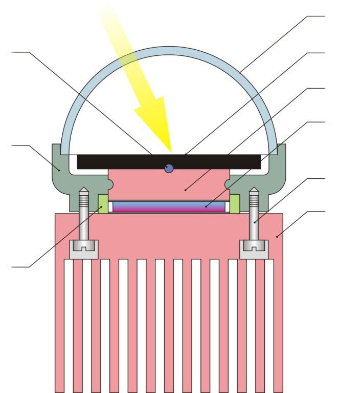
The sensor consists of a molded plastic case , a copper heat conductor is embedded in the manufacturing stage, and a blackened copper plate is attached to it. A thermal sensor is placed in the slot between the plate and the heat conductor. The space in front of the plate is covered with a glass dome, which is hermetically installed in a special recess on the body. To eliminate the effect of heat loss through the dome and the walls of the housing, the internal space of the sensor is evacuated. A thermal module is installed in the lower part of the case between the heat conductor and the copper finned heat sink. Before installation, a special thermal grease is applied to the working surfaces of the thermal module, which ensures reliable heat transfer at the points of contact. The radiator is attached to the housing with screws made of a material with a high thermal resistance (for example, plastic). To prevent contact of the thermal module with the outside air, between the casing and the radiator fit insulating gasket. Also, a second thermal sensor and a cable connector (not shown in the figure) are mounted on the case.
Солнечные коллекторы
Солнечные коллекторы
Солнечные коллекторы
Thermal sensor
Blackened plate
Thermal sensor
Heat conductor
Thermal module Peltier
Case
Fastender
Radiator
Thermal pad
Description of the device
The actinometer consists of a remote sensor connected via connectors with a six-core cable to the measuring unit. The measuring unit also has a connector for connection to a computer via a COM port and a connector for a power cord (not shown in the figure).
t 1 , t 2 - thermal sensors; ТЭМ - thermoelectric module; I d - current sensor; БУ - control unit; РТ - current regulator;
ИП- DC power supply; ПР - converter; ИФ - interface for communication with a computer.
ИП- DC power supply; ПР - converter; ИФ - interface for communication with a computer.
The actinometer sensor has two thermal sensors: t 1 - for measuring the temperature of a blackened plate and t 2 - for measuring the temperature of the sensor body. In the absence of solar radiation, the plate temperature is equal to the case temperature, i.e. outdoor temperature. The signals from the temperature sensors arrive at the comparator of the control unit ( БУ ) that controls the current regulator ( РТ ). In case of equality of signals from thermal sensors, the current in the power supply circuit of the thermal module ( ТЭМ ) is zero. When solar radiation hits the plate, it is heated, which is detected by the temperature sensor t 1 . And if t 1 > t 2, БУ via РТ supplies a current from the power source ИП at the thermal module, which starts to heat extraction from the sensor plate. When this begins to receive information from a current sensor I d , which through the converter РТ and the interface ИФ is fed to the computer PC , where it is processing and recording. As the plate cools, the current through the thermal module decreases, and when the readings of the temperature sensors equalize ( t 1 = t 2 ), the cooling process stabilizes. By reducing the intensity of solar radiation when t 1 < t 2, the current through the thermal module begins to decrease until the heat balance is restored again ( t 1 = t 2). With an increase in the intensity of solar radiation, the process repeats.
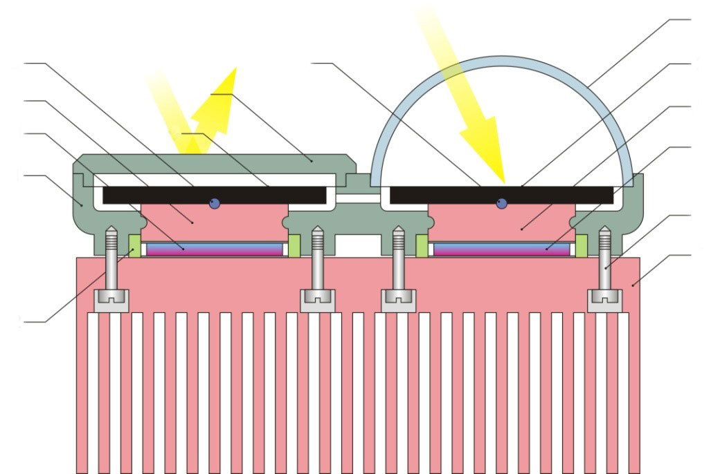
To reduce the temperature dependence and increase the measurement accuracy, another sensor design has been developed and proposed for research.
The sensor consists of two chambers, united in one case with identical plates, thermal sensors, thermal conductors and thermal modules. In this case, one plate is under the glass dome, and the second is covered with an opaque cover with a reflective outer surface to prevent the body from heating. This design will compensate for the effect of heating (or cooling) of the case on the accuracy of measurements.
The sensor consists of two chambers, united in one case with identical plates, thermal sensors, thermal conductors and thermal modules. In this case, one plate is under the glass dome, and the second is covered with an opaque cover with a reflective outer surface to prevent the body from heating. This design will compensate for the effect of heating (or cooling) of the case on the accuracy of measurements.
Солнечные коллекторы
Солнечные коллекторы
Солнечные коллекторы
Glass dome
Blackend plate
Blackend plate
Lit
Thermal sensor
Blackend plate
Thermal sensror
Heat conductor
Thermal module Peltier
Thermal module Peltier
Case
Thermal insulation pad
Fastender
Radiator
Consider the work of this variant of the actinometer. As can be seen from the block diagram, the device contains two absolutely identical thermal modules ТЭМ1 and ТЭМ 2 with the corresponding current regulators URT , controlled by signals from temperature sensors t 1 and t 2 . The principle of operation of this actinometer is the same as that of the previous one, with the only difference that the amount of solar radiation is determined by the difference in currents passing through the thermoelements.
t1, t2 – термодатчики; ТЭМ1, ТЭМ2 – термоэлектрические модули; И – измеритель дифференциального тока; УРТ – управляемый регулятор тока; ИП – источник питания постоянного тока; ПР – преобразователь; ИФ – интерфейс для связи с компьютером.
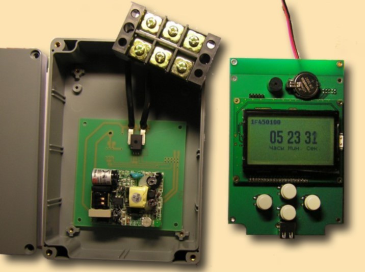
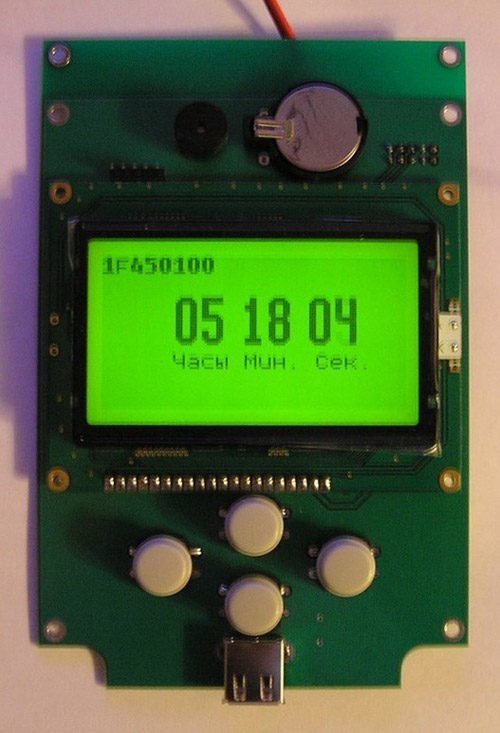
Registrar of electricity consumption
This device allows you to autonomously record the dynamics of electricity consumption in the house. Every fifteen seconds, the current is measured in the network, and the measurement results are recorded in the memory of the recorder. Every two months, the accumulated data through the USB port can be "dumped" to a Flash-card or directly to a hard disk of a computer for further processing of the received information.